I believe that every engineer's dream is to design and build something that will travel into space and beyond, to boldly go where no one has gone before. At least my dream was to create a product that will be used in either the space or aerospace industry. I was lucky enough to be part of one such space project. In 2014, my colleague invited me to get involved in a project to design a moon rover. This project was part of the Google Lunar X Prize, and we were part of a small international team called Team Stellar. My colleague and I were the only two mechanical engineers on the project, so the whole burden of designing Rover’s mechanical systems was on our shoulders.

A brief history of planetary rovers
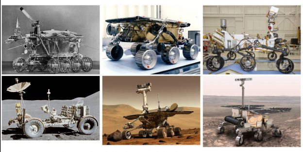
Did you know that first ever roving remote-controlled robot to land on any celestial body was the Soviet Lunokhod 1 back in 1970? What's even more interesting is that its big brother, Lunokhod 2, held the record of the longest travel of any celestial body, traveling over 39 km (24.2 miles) on the Moon. Only recently in July 2014, did the Mars rover Opportunity brake this record by traveling more than 40.25 km (25.1 miles). Opportunity has currently covered an impressive distance of 43.44 km (26.99 miles) as of 4th October 2016.
From and engineering standpoint, Lunokhod was designed to be simple and functional. Since the Soviets didn’t have the resources or technical expertise to make space hardened electronics, they decided to create a vacuum-sealed vessel and put all the electronic inside, to be protected from the space environment. This is why Lunokhod body looks like a bathtub with eight wheels, making it a more redundant system.
It is interesting that almost 40 years later, there weren't any more attempts to send the robot to the Moon.
In December 2013, the Chinese moon rover called Yutu (Jade Rabbit) landed on the Moon surface and was operational until the second lunar night, when it encountered difficulties, but continued to gather information until July 2016.

History of Planetary Rovers, from left; first generation LunokHod / LRV, Second generation Sojourner / Opportunity, Third generation Curiosity / ExoMars
So how do you design a moon rover?
Like any other engineering project, you start with a project description and goals. To win the Google Lunar X Prize, there are three mission objectives. The first goal was to drive 500m on Moon surface during the day, a secondary objective is to drive 5000m on Moon surface during the day, and an additional objective is to survive Lunar night. So our goal was to develop and design the rover who will operate on Moon surface, drive 5000m and survive Lunar night (temperature over Lunar night drops to -153 C). On the Lunar surface, the terrain is composed mostly of fine-grained soil called regolith in which Rover may easily get stuck, and the gravity is smaller than on Earth, causing the rover to bounces more dynamically.
Also, the rover must be able to traverse flat plains as well as rock covered areas that require a high degree of mobility and stability. In the end, the mobility system must be reliable and remain at a relatively high efficiency for the period of operation to achieve all of the mission objectives.
After the project goals were defined, we roughly created the concept of the Rover mechanical systems. The body, suspension, wheels, and drivetrain were the major mechanical elements that make up the rover vehicle. The body houses the electronics and batteries and serves as a mounting place for all other systems. The suspension lifts the body above the wheels to maximize ground clearance improving mobility over obstacles.
The rover used a differential mechanism to maintain a relatively even weight distribution on all wheels when driving over uneven terrain. The drivetrain transfers torque from the motors to the wheels using gear trains. The wheels transfer torque from drivetrain to terrain and propeller vehicle, moving it forward or reverse.
Given the project goals, we quickly realized that our primary focus will be on wheeled locomotion system. My task was to design wheels and create the concept of the suspension system.

Moon rover suspension
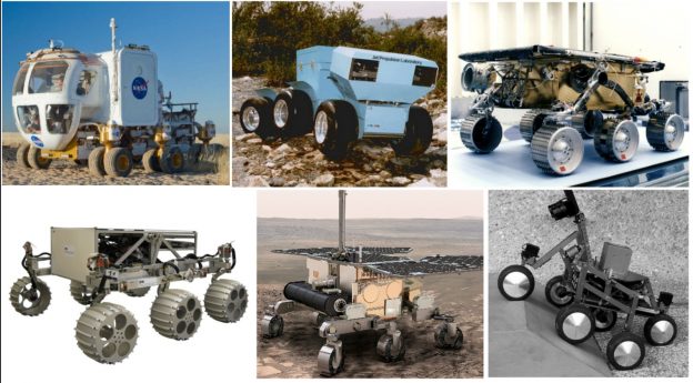
The primary role of the suspension subsystem is to provide the rover with a mobility system that has the kinematic range to permit the Rover to safely traverse obstacles and allow the wheel assemblies to rotate for Rover steering maneuvers. The key to the success of any wheeled locomotion system is that adequate traction is always maintained between wheels and surface. I have considered only two main types; the six-wheeled and four-wheeled suspension. The eight-wheeled suspension was obviously overkilling for this kind of project, and three wheel was risky because it has too small redundancy.
A lot of research was done on six-wheeled suspension, so I started with that. I have selected only two six-wheeled suspension type to have focused on my concept design. Other six-wheeled suspensions types I have researched offered poor performances and didn’t offer almost any advantage.

Six Wheels suspension types, from left; Independent suspension, articulated body suspensions, rocker-bogie suspension, crab suspension, 3-bogie suspension and shrimp hybrid six wheel suspension.
The first design type I have looked was a six-wheeled, rocker-bogie suspension. This suspension is a mechanism that, along with a differential, enables a six-wheeled vehicle to passively keep all six wheels in contact with a surface even when driving on severely uneven terrain. This is still NASA’s favorite suspension type, and all three Mars rovers have it.
The second type was a three bogie suspension system. The so-called “3 bogies” is based on three simple bogies located at each side of the rover and on the rear (i.e. longitudinal bogie). The three points attachment is a defined system that allows to passively keep all six wheels in contact with the ground, even on an uneven terrain. Also, by adding actuators for deployment on each deployment joint, this suspension is capable of walking motion, giving more mobility over rocker-bogie suspension system.
The four-wheeled suspension is very similar to the six-wheeled but much simpler. The main advantage of a four-wheeled suspensions is obviously simple design, less weight, and less power consumption (since it uses fewer motors for steering and moving).
I considered three main types: the rocker-bogie suspension (which is the same as six-wheeled), longitudinal bogie suspension, and semi-independent suspension. The third type is a hybrid version using independent suspension and rocker-bogie suspension, combining advantages of both.

Final concept selection
It wasn’t an easy task to select the best concept for the Moon rover project. But with a little help from a concept generation matrix, along with a risk assessment, I made a decision.
I opted for the concept with 3-bogie suspension. There are several reasons I selected this concept. Comparing to the other designs, the 3-bogie suspension advantage is the lower mass of linear suspension beams, the simplicity of design, meaning lower manufacturing cost, and lower power consumption (only have six motors for steering and moving, comparing to 12 motors of six-wheeled rocker-bogie suspension). But at the same time providing enough traction for rover on the lunar soft regolith terrain and applying equilibrated pressure on the soil.

As at that stage of development we didn’t have fully defined mechanical design parameters, I looked also at the possibility of modular design. With 3-bogies, the suspension could be divided into two main suspension modules. The main module was front left and right rocker bogies which serve as the base of the four-wheeled design. The rear bogie was the second module, which can be added to Rover body, turning four-wheeled design into six-wheeled.
Lessons learned
This was one of the challenging and most exciting project in my professional career. Who wouldn’t love to design a rover vehicle for another planet? What I have learned is that simplest solutions are the best ones. The same mechanical principles also apply to the aerospace design too. The difference is in material use, surface finish, and surface protection.
Did it make to the Moon? The Google Lunar X Prize is still happening, and all teams that made it to the last stage still didn’t launch their Rovers to the Moon. Unfortunately, our team Stellar ran out of funding, so we had to drop the project at half the way point.
Nevertheless, I enjoyed every minute I spent working on it. Hopefully, there will be more opportunities in the near future to work on more aerospace projects.
Like what you've just read? Sign up to receive GrabCAD's free weekly Digital Thread newsletter.
We're making professional 3D printing easy and accessible
GrabCAD Print, our new 3D printing app, is currently in beta. Want to help us test it? Click here or on the graphic to the left to request updates and beta access.


